2001 Yamaha R6 Wiring Diagram
The signal wire from the speed sensor is white. That I believe is pretty much a standard for speed sensor wiring. +12V to the speed sensor is yellow/blue which comes from the tacho for some reason. It looks like the speed wire changes colour on the 00-01 at the meter connector. R1_2000_red Discussion starter.

Yzf R1 Wire Diagram / 1 Entdecke rezepte, einrichtungsideen
The original wires from the ignition are: (Thick) Red, Brown, Orange. (Thin) Blue, Blue with Yellow stripe. I cut the wiring harness 2 inches from the ignition switch so I'd have plenty of wire to work with for the splice.

2008 R6 Wiring Harness Diagram
2005 Yamaha YZF-R1. Been off the road for approx 9 weeks now it wont start changed spark plugs changed coil pack and fuel pump is working theres sparks there just wont fire up. Be the first to answer 1999 Yamaha YZF-R1. May 05, 2014 • 1999 Yamaha YZF-R1.

1999 Yamaha R1 Wiring Diagram DIAGRAM 1999 Yamaha R1 Wiring Diagram
Yamaha Motorcycle Wiring Color Codes, Wiring Diagram. Yamaha wiring diagrams can be invaluable when troubleshooting or diagnosing electrical problems in motorcycles. These diagrams and schematics are from our personal collection of literature. Need to Know pages for tools required to work on electrical systems.

Yzf R1 Wire Diagram 1999 Yamaha R1 Wiring Diagram Jvc Wiring
Whether you have recently received a freshly converted harness or are working with a more seasoned harness, you may find it useful to familiarize yourself with the harness and the different connectors that it is comprised of. This guide is focused on the wiring harness for a 2009 - 2011 Yamaha R1.
[DIAGRAM] Yamaha R1 Wiring Diagram 1999
I replaced the fuse because it was burnt out and I discovered that there was a loose wire or something because the lights started to work intermittently, however with the signal on, the opposite tail light would flash red.

Yamaha R1 Wiring Diagram
Page 1 2020 SERVICE MANUAL YZF-R1 YZF-R1M YZFR1L YZFR1LC YZFR1ML YZF1MLC LIT-11616-33-33 B3L-28197-10.; Page 3 If there is any question about a service procedure, it is imperative that you contact a Yamaha dealer for any service information changes that apply to this model. This policy is intended to provide the customer with the most satisfaction from their vehicle and to conform to federal.

Yamaha R1 Wiring Diagram 1999 Wiring Diagram and Schematic
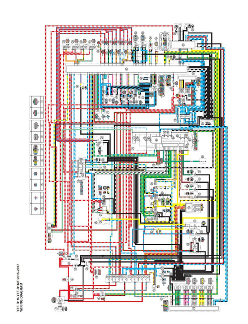
The diagram will provide an overview of the entire electrical system of your bike, including the wiring layout and connections between various components. It will also show you where each wire should be connected, as well as the voltage and current ratings of each component.

Yamaha R1 Ignition Wiring Diagram diagramwirings
Page 155: Removing The Cylinder Head. CYLINDER HEAD EB402102 REMOVING THE CYLINDER HEAD 1. Remove: • cylinder head bolts • cylinder head nuts NOTE: Loosen each bolt and nut 1/2 of a turn at a time, in stages and in a crisscross pat- tern. After all of the bolts and nuts are fully loosened, remove them.

Yamaha R1 Ignition Wiring Diagram diagramwirings
Understanding these components will help you better understand how the bike's electrical system works. First, there are the three main components that make up the Yamaha YZF R1 wiring system: the battery, the stator, and the regulator rectifier. The battery supplies power to the stator, which converts it into alternating current (AC).

1999 Yamaha R1 Wiring Diagram
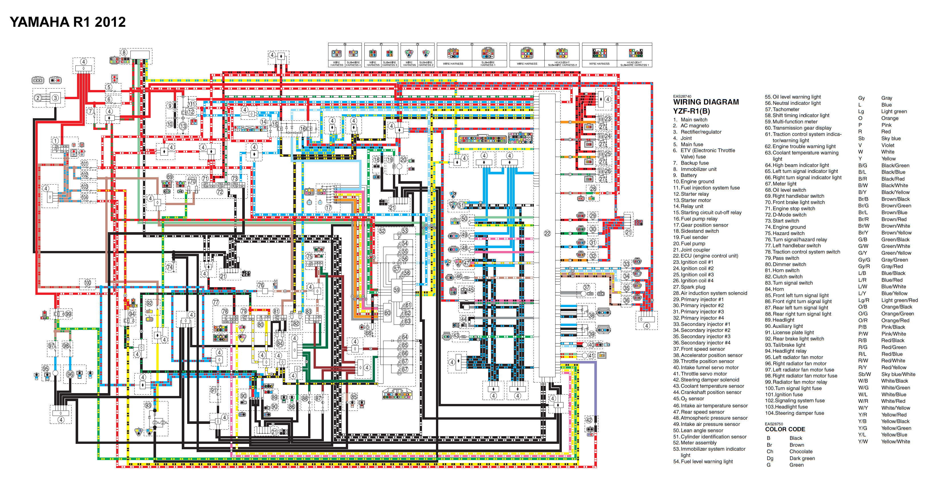
WIRING DIAGRAM YZF-R1(W) 2007 1. Main switch 2. AC magneto 3. Rectifier/regulator 4. Main fuse 5. Backup fuse 6. Immobilizer unit 7. ETV fuse 8. Battery 9. Fuel injection system fuse 10.Starter relay 11.Starter motor 12.Starting circuit cut-off relay 13.Neutral switch 14.Sidestand switch 15.Fuel pump 16.Throttle position sensor (for throttle.

Complete Electrical Wiring Diagram Of Yamaha Yzf R1 Wiring Diagram
By following the detailed instructions in the diagram, you can make sure that your motorcycle is running smoothly and efficiently. The Yamaha YZF R1 complete electrical wiring diagram is an invaluable tool for anyone looking to understand and maintain their Yamaha YZF R1.
Yamaha R1 Wiring Diagram 2003 Wiring Diagram and Schematic Role
Install the wire harness from the kit by reference to the service manual. 3. Pass the wire harness through the hole in the cable holder side and secure it with a clamp at the location indicated. Page 56 NOTICE When the oil catcher tank is in use, change the direction of the hose clip so it won't touch the wire harness.
[DIAGRAM] Yamaha R1 Wiring Diagram 1999
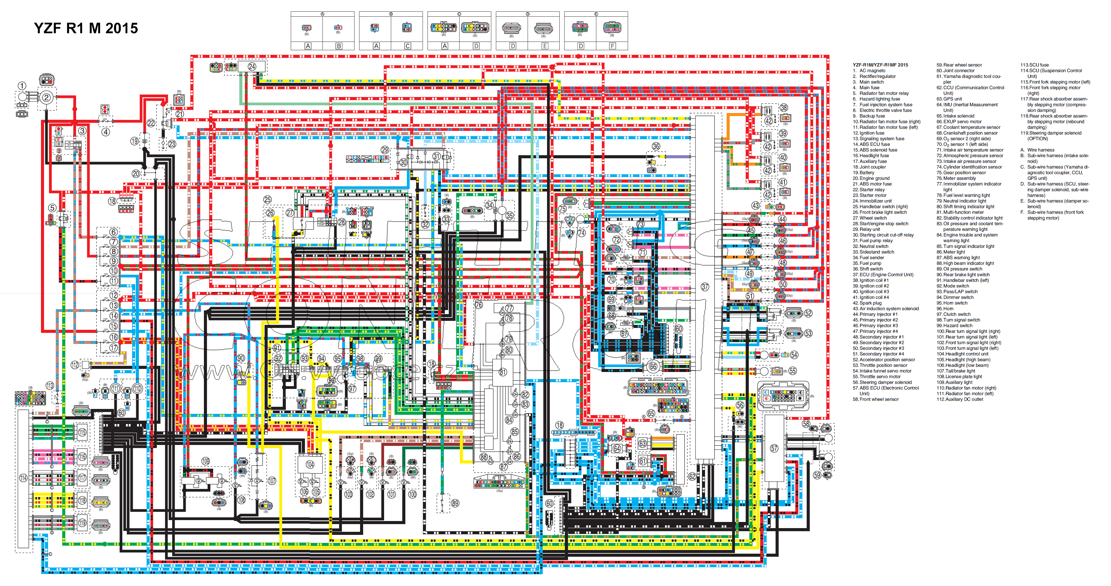
The 99 Yamaha R1 wiring diagram should show all the connections between each component in the electrical system, so you can quickly identify any issues or make the best use of the wiring. Pins and plugs are usually indicated by lines on the diagram and follow their respective positions in the connector port.

2000 yamaha r1 wiring diagram
View and Download Yamaha YZF-R1 98 service manual online. YZF-R1 98 motorcycle pdf manual download. Also for: 4xv1-ae1.
[DIAGRAM] Yamaha R1 Wiring Diagram 1999
Service manual Yamaha YZF-R1 Service Manual Also See for YZF-R1: Service manual (808 pages) , Owner's manual (130 pages) , Manual (82 pages) 1 2 Table Of Contents 3 4 5 6 7 8 9 10 11 12 13 14 15 16 17 18 19 20 21 22 23 24 25